IMU Sensor Fusion With Wheel Odometry in Ground Robots
Combining inertial and wheel measurements lets robots navigate when either sensor alone would fail.
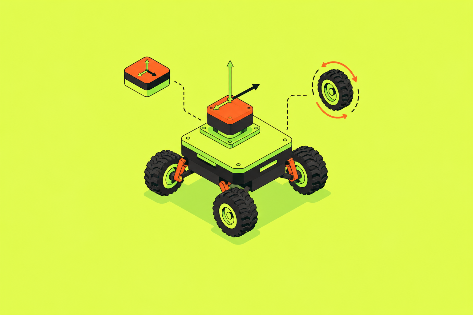
IMU sensor fusion with wheel odometry gives ground robots a pose estimate they can trust more because the sensors fail in different ways. High-rate inertial measurements help bridge wheel slip, while encoder velocity measurements constrain IMU drift. The design task is to preserve that complementary relationship through calibration, uncertainty modeling, and selective rejection of unreliable measurements.
Why IMU and wheel odometry fail in opposite, predictable ways
Gyroscope and accelerometer biases accumulate as IMU measurements are integrated, so orientation and position errors grow even during normal motion. Wheel encoders fail differently. They report useful velocity on flat, grippy surfaces, but when a wheel slips, its rotation does not produce the expected translation. The encoder cannot distinguish free spinning from motion across the ground, so its inferred velocity can become wrong abruptly.
That difference gives fusion its physical basis. IMU drift is slow and cumulative, while wheel slip is abrupt and episodic, so their errors rarely compound at the same moment. During a brief slip, inertial measurements still show short-term motion and changes in attitude. Under normal traction, wheel velocity provides a reference that does not depend on integrating acceleration.
What each sensor actually contributes to a fused pose estimate
The IMU supplies linear acceleration and angular velocity, typically at 100 Hz or higher. Those measurements allow pose propagation between the slower corrections. A sharp turn or a bump can change the robot’s attitude faster than encoder pulses alone can resolve, making the inertial signal valuable precisely where wheel measurements lack detail. Encoders, by contrast, supply velocity derived from pulse counts without accumulating acceleration-integration error under normal traction.
The division of labor is therefore specific. The IMU predicts attitude as it changes quickly, while encoders anchor velocity on the ground plane, so together they constrain the six-degree-of-freedom pose more tightly than either can alone. These signals are useful only if their physical relationship is known. Intrinsic and extrinsic calibration provide that relationship, including wheel radius and the alignment between sensor frames. An incorrect radius or misaligned IMU changes what the measurements mean before any fusion algorithm receives them.
How a filter turns complementary signals into a single pose estimate
The Extended Kalman Filter is the standard starting point because its prediction-and-correction cycle matches the measurement flow. IMU readings propagate the pose at high rate, while uncertainty grows between encoder updates as bias is integrated. When an encoder velocity measurement arrives, the filter computes the residual between predicted and measured velocity. It then corrects the estimate according to the relative covariance of the prediction and measurement.
This is a continuous Bayesian estimation loop. Encoder data does not simply join the inertial data in an average, but periodically constrains the velocity error that would otherwise accumulate. Operationally, the covariance matrix describes estimated uncertainty in the state and how errors in its components relate to one another. Its usefulness extends beyond the estimator because planning decisions can depend on how confidently the robot knows its pose.
IMU preintegration summarizes many high-frequency measurements into a compact factor rather than recomputing the full integral during each optimization iteration. This is especially useful when inertial data is combined with slower measurements such as LiDAR point clouds.
Where the EKF assumption breaks down and what that costs
A conventional wheel-IMU EKF depends on a known, fixed wheel kinematic model. On flat, uniform terrain, its local linearization of nonlinear dynamics works well. Large slip changes that relationship. Encoder errors then depend on terrain and contact conditions in nonlinear ways that a static noise model cannot capture well. Increasing a fixed noise value does not make the underlying motion model adapt to the surface.
Terrain also changes which directions are uncertain. Height, roll, and pitch uncertainty can be low on flat ground but large on uneven terrain, requiring the wheel contribution to be reweighted accordingly. The M3DGR benchmark, introduced with Ground-Fusion++, covers wheel slippage, visual challenge, LiDAR degeneracy, and GNSS denial. It shows that most wheel-odometry-integrated algorithms drift a great deal when wheels slip.
Calibration adds another source of model mismatch. Incorrect wheel radius and IMU drift accumulate over time, while tire wear or load changes can undermine tuning that worked at startup. A warehouse aisle and a loading dock ramp can therefore expose very different behavior from the same sensors and filter. The limitation lies in the assumptions attached to the measurements.
The loose-coupling vs. tight-coupling decision and what rides on it
Loose coupling turns each sensor’s measurements into a pose estimate on its own before combining the estimates. This simplifies implementation but discards cross-sensor correlations and can compound errors already absorbed by each subsystem. Tight coupling puts raw measurements into one estimator, keeping information that is lost when pose estimates are made separately. That usually makes the estimate more accurate in difficult conditions, but timing, calibration, and noise modeling must be consistent.
Measurement access also changes how faults can be handled. Ground-Fusion++ uses modular coupling of GNSS, RGB-D, IMU, wheel odometry, and LiDAR. Its wheel anomaly detector removes observations that cannot be trusted before they enter the state estimate. Pose-level fusion has a harder time doing this once a bad observation has already shaped a subsystem’s output.
However, late fusion offers stronger fault isolation. A bad camera can be contained without corrupting the wheel-IMU estimate, which is a genuine advantage where faults must remain separated. Rahimipour’s August 2025 SMU thesis evaluated EKF strategies for a retail robot using wheel encoders, an IMU, and stereo visual odometry in GPS-denied indoor environments. Orientation-only visual updates achieved the highest localization accuracy, showing that measurement selection can be as consequential as architecture. The decision rule is tight coupling for maximum accuracy on known, well-calibrated hardware, and loose coupling when modularity or fault isolation takes priority.
Factor graphs as an alternative to filter-based fusion and when they are worth the cost
Factor graphs change how the estimator handles history. They represent measurements and robot states as probabilistic constraints, allowing an optimizer to revise earlier states when new information arrives. GTSAM with iSAM2 supports this relinearization, whereas a sequential EKF cannot revise its past trajectory in the same way. When a robot revisits a location, a graph can propagate a loop-closure correction backward through earlier drift.
That flexibility has a computational cost. A 2025 GNSS/IMU factor graph study reported an average iSAM2 processing time of 0.039 seconds per epoch, supporting real-time feasibility for compact state spaces. The time needed for larger graphs with dense inertial constraints grows differently, so that result cannot guarantee the timing for all graphs. Preintegration helps by preventing graph growth from tracking every individual IMU sample.
An EKF is likely sufficient for a bounded indoor space on a known map. Long outdoor trajectories with loop closures make factor graphs more compelling because revising history can correct errors that a forward-only estimate retains. They can also handle non-Gaussian noise, but they still need measurement models that fit.
What wheel-mounted IMUs change about the sensor placement assumption
Architecture determines how signals are combined, but placement changes the signals themselves. A body-mounted IMU measures acceleration and angular velocity in the body frame, and sensor-frame gyro bias builds up into heading error as it is integrated. Mounting the IMU on a wheel changes that mechanism. As the wheel keeps turning, its rotation modulates gyro bias, which averages out its constant component and reduces the low-frequency noise that adds to heading drift.
Wheel rotation also becomes a useful measurement. The inertial signal provides wheel angular velocity that can supplement or replace encoder pulses for dead-reckoning. The Wheel-Mounted Inertial (WMI) Dataset, published in Nature Scientific Data in 2025, provides measurements from all four wheels and the vehicle body with an associated ground truth trajectory. It offers a benchmark for evaluating this physical configuration rather than assuming the chassis is the only useful mounting location.
A 2026 University of Haifa study demonstrated a hybrid neural-inertial framework combining wheel-mounted IMUs with GNSS in an error-state EKF. It reported approximately 46% lower position root mean squared error than standard wheel-mounted inertial fusion with GNSS updates. That result applies to the combined framework. Wheel mounting also exposes sensors to harsher vibration, can require slip-ring or wireless data links, and demands careful wheel-to-body extrinsic calibration.
Learned kinematic models as a replacement for hand-tuned noise parameters
Wheel mounting changes bias behavior, but terrain-dependent slip still challenges the kinematic model. Classical estimators specify the relationship between encoder velocity and body motion at design time, often with fixed noise covariances. On complex terrain, that relationship can be structurally wrong. A learned model changes the mapping itself, while a fixed mapping only allows changes in how much it is trusted.
Okawara et al.’s January 2025 paper in Robotics and Autonomous Systems developed a LiDAR-IMU-wheel odometry algorithm with a “neural adaptive odometry factor” inside a GTSAM factor graph. The network trains online during state estimation and does not need labeled terrain data. Its parameter vector is a graph node, so the measurements that constrain pose also constrain the network’s weights and biases. This lets the kinematic model adapt to the terrain as it is now.
Online adaptation introduces its own failure window. Training takes extra computing work, and a model fitted to recent terrain can become confidently wrong as soon as the surface changes. In this approach, when the model disagrees with other measurements, the residuals grow, so the uncertainty model can give the kinematic factor less weight. That safeguard makes learned fusion a promising research direction.
Adaptive sensor selection when one modality becomes unreliable mid-mission
A calibrated architecture still needs to respond when a sensor degrades during operation. Fixed-weight fusion assumes that sensors work as expected, so a lifted wheel or a camera saturated by sunlight can pull the estimate toward a wrong result that it trusts too much. Keeping those measurements in use can be worse than leaving them out for a while. The selection decision must therefore distinguish a useful observation from one that no longer matches its assumed uncertainty.
Residuals provide a basis for that distinction. When wheel velocity disagrees with the prediction beyond a threshold relative to estimated uncertainty, an anomaly detector can flag the observation as unreliable. A 2025 adaptive localization study for indoor forklift AGVs proposed dynamically changing fusion weights according to real-time sensor confidence in complex warehouse environments.
This returns to the original reason for combining the sensors. When wheel measurements fail abruptly, the IMU can still provide reliable short-term attitude, while valid encoder velocity constrains the inertial estimate during normal traction. When uncertainty rises, the planner can respond to a pose it cannot trust by slowing down, widening safety margins, or triggering re-localization.
Practical implementation choices for a ground robot pose estimator
Before choosing a more elaborate estimator, establish wheel radius, IMU frame alignment, and synchronized timestamps. These are common failure sources independent of architecture. For most flat-terrain indoor robots, start with an EKF using IMU prediction, encoder velocity updates, and explicit IMU bias states.
Then set covariances that match how the sensors actually behave. Over-trusting encoders lets slip corrupt the estimate, while over-trusting the IMU allows drift to outpace wheel corrections. If that baseline cannot handle long missions, frequent slip, or outdoor loop closures, consider tighter coupling or a factor graph. Keep fault isolation in the decision when localization downtime or sensor contamination is unacceptable.
FusionCore, a 2026 open-source ROS 2 implementation, accepts raw IMU data, differential-drive and Ackermann wheel odometry, dual-antenna GNSS heading, and visual odometry or SLAM poses. It models or detects wheel slip. For terrain that changes, the online-learning approach and the framework’s wheel anomaly detection are open-source starting points for research, though neither is an established default for production use. Choose according to terrain variability, compute budget, and tolerance for localization downtime, with each sensor’s failure behavior determining how much authority its measurements receive.
Sources
- Wheel-Mounted/GNSS Fusion with AI-Aided Position Updates
Provided the 46% lower position RMSE figure from the University of Haifa hybrid neural-inertial framework combining wheel-mounted IMUs with GNSS.
- Towards Robust Sensor-Fusion Ground SLAM: A Comprehensive Benchmark and A Resilient Framework
Described the M3DGR benchmark and Ground-Fusion++ framework, including the wheel anomaly detector and modular sensor coupling approach.
- Research on Multi-Sensor Fusion Localization for Forklift AGV Based on Adaptive Weight Extended Kalman Filter
Provided the example of a 2025 adaptive localization study for indoor forklift AGVs that dynamically adjusts fusion weights based on real-time sensor confidence.
- Development of Autonomous Robot with Multi-Sensor Fusion for
Provided details on the SMU thesis evaluating EKF strategies with wheel encoders, IMU, and stereo visual odometry in GPS-denied indoor environments, including the finding that orientation-only visual updates achieved highest accuracy.
- Wheel-Mounted Inertial Datasets
Provided details on the Wheel-Mounted Inertial Dataset published in Nature Scientific Data in 2025, covering measurements from all four wheels and vehicle body with ground truth trajectory.