Differential Drive Wheel Module Design and Sizing
How to sequence wheel diameter, track width, and motor sizing to avoid drift and tip-over.
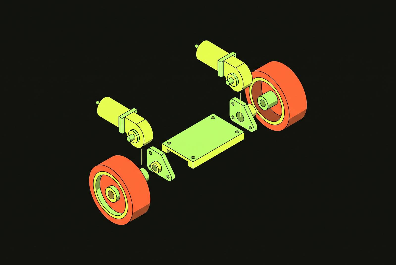
Designing a differential drive wheel module is a chain of decisions: wheel diameter, track width, motor torque, and load each constrain the next, and the order in which you solve them determines how the finished robot moves. Skipping a step, or sizing one parameter in isolation, causes the error to appear later as drift, stall, or a robot that tips over on its first turn. Differential Drive Wheel Module Design and Sizing.
Differential drive and the design decisions its simplicity creates
Everything a differential drive robot does traces back to two numbers: linear velocity (V) and angular velocity (ω). Every wheel, motor, and gear ratio in the design exists to deliver some combination of those two values accurately and repeatably. The canonical hardware layout backing this up is simple: two independently driven wheels, plus one or more passive casters that provide balance and ground contact but no drive force of their own.
Commanding both wheels the same speed and direction makes the robot go straight. Command different speeds, and it arcs. Command equal speeds in opposite directions, and it spins in place around its own center. None of this requires steering linkages, a differential gearset, or the mechanical complexity of an automotive drivetrain, which is exactly the appeal.
The robot cannot slide sideways. That non-holonomic constraint separates differential drive from omnidirectional platforms, and it means every sizing decision downstream, wheel diameter, track width, motor selection, has to work within a system that can only move along the arc its two wheel speeds define. Because wheel size, track width, and motor torque are all coupled through the same kinematic equations, changing one after the fact means re-checking all of them. This piece works through that sequence in the order an engineer would actually have to solve it: wheel diameter, track width, kinematics, load, motor sizing, encoders, casters, and finally the control corrections that clean up what the mechanics alone can't fix. Higher-level path planning sits outside this scope entirely.
Wheel diameter: how terrain, speed, and obstacle clearance set the first constraint
Wheel diameter is usually the first number picked, and it comes with a built-in tension. A larger wheel delivers higher top speed for a given motor RPM and more ground clearance, both of which read as unambiguous wins on a spec sheet. But the same larger wheel demands more torque at the motor shaft to produce the same force at the ground, so the diameter decision immediately taxes the motor sizing that comes later.
Terrain sets the practical floor for this number. Wheel diameter has to clear the tallest obstacle or surface irregularity the robot is expected to cross, with enough margin that a curb lip or a expansion joint doesn't stop the robot cold. Built examples bear this out at different scales. The MAVI-BOT platform, described in Karakaya's 2022 paper in the Global Journal of Computer Sciences, used pneumatic wheels 22 cm in diameter and 6 cm thick on its front active wheels. SphereX, a planetary robot, used wheels 20 cm in diameter, a size driven by the rough, unstructured terrain planetary rovers are built to cross.
That width dimension deserves attention alongside diameter. A wheel that's wide relative to its diameter smears its contact patch across a larger area during a point turn, and that smearing adds uncertainty to where the actual pivot axis sits. Thinner wheels reduce that variability. Competition builders gravitate toward them even at some cost in load capacity.
Tire construction adds a wrinkle that's easy to miss on a spec sheet. Pneumatic wheels deform under load, and that deformation changes the effective rolling radius from one moment to the next. Solid wheels don't have this problem, but they trade it for less cushioning on rough terrain, so the diameter chosen up front isn't fully final. It has to be revisited once motor speed and gear ratio are known, because the combination of all three must deliver the target linear velocity. In competition builds, BaneBots T61 10A 2–3/8″ wheels were selected, with builders noting that thinner wheels reduce variability in the pivot point during spin turns.
Track width: the stability-agility trade-off and the definition of wheelbase measurement
Track width L is the distance between the contact points of the two driven wheels on the ground (for flat tires this is center-to-center), and the measurement convention matters because L appears in every kinematic formula. Measuring it wrong, or measuring it inconsistently between the physical robot and the firmware constant, propagates the error into every turn the robot ever executes.
The trade-off track width controls is stability against agility. A narrow track turns fast and pulls less current doing it, but it tips more easily, particularly around the caster during aggressive maneuvers. A wide track is the opposite: stable, resistant to tipping, but slow to rotate and hungrier for current when it does. For four-wheel differential layouts specifically, the sources note that performance is optimized when the wheelbase is square or nearly square, front-to-back distance close to side-to-side distance.
The robot starts tipping around its caster on anything but a flat, smooth floor when the track is narrower. Turning gets sluggish when the track is wider, drawing more current than the application probably budgets for. This isn't a number to pick in isolation, either: a track that's wide relative to wheel diameter buys stability at the cost of rotational agility, while a track that's narrow relative to diameter risks tip-over the moment the floor isn't perfectly flat.
Footprint constraints from the broader environment can override both of these considerations. YOR isn't differential drive, but the constraint it illustrates applies regardless of drive architecture: if the robot has to move through doorways and around furniture, footprint sets an upper bound on track width that no amount of stability analysis can override. YOR (arXiv 2602.11150) reports a footprint reference of 43 × 34.5 cm for a swerve-drive platform, not differential, illustrating how footprint constraints in cluttered indoor spaces set an upper bound on track width regardless of drive type.
Whatever value gets chosen for L, it needs to be documented precisely, because the next section uses it verbatim, not approximately, in the equations that convert commanded motion into wheel speeds. For small hobby/research robots weighing roughly 0.5 kg–2 kg, a practical track width in the range of roughly 10–20 cm works well, since below that the robot tips easily around the caster and above that turning becomes slow and motor-current-intensive. In the interaction with wheel diameter, a wider track relative to wheel diameter makes the robot stable but sluggish in rotation, while a narrow track relative to diameter risks tip-over on uneven ground; the designer is balancing two ratios simultaneously.
The kinematics linking wheel diameter and track width to actual wheel speeds
Forward kinematics takes the left wheel velocity V_L and right wheel velocity V_R the robot is executing and computes the resulting linear velocity V and angular velocity ω, answering where the robot is going. Inverse kinematics runs the other way: given a desired V and ω, it computes the V_L and V_R the motor controller needs to command.
Both directions use wheel radius r and track width L directly. Any error in measuring either one becomes a systematic motion error baked into the math itself. No amount of software tuning fixes a wrong L value; it just makes the robot confidently wrong instead of randomly wrong.
There's a clean diagnostic test built into the geometry. Command V_L equal and opposite to V_R and the robot should rotate exactly in place, with no net translation at all. If it drifts sideways or fails to close the circle, the first suspects are L measurement error or tire deformation under load.
In practice, a high-level controller issues (V, ω) commands, ROS's cmd_vel Twist message being a common real-world example, and the motor driver applies the inverse kinematics equations to produce per-wheel PWM values. The Motor-Based Model assigns one transfer function per motor, which is more accurate and better suited to SLAM and precise localization work. The Simplified Model uses two transfer functions, one linear and one angular, which costs less computationally and suits embedded systems with limited resources.
Once wheel diameter and track width are locked into these equations, they're locked into the controller too. Changing either one physically requires the controller to be re-tuned to match, not just a firmware constant update. Two modeling approaches emerge from the research. MBM consistently outperformed SM in odometry accuracy, making the choice between them a resource/accuracy trade-off rather than purely a software decision.
Load analysis: establishing the force budget that motor torque must meet
Motor sizing starts with an honest accounting of mass, and it's easy to get wrong by leaving something out. Payload, chassis, batteries, and sensors all count toward total robot mass, and underestimating any of them propagates as an underestimate through every torque figure calculated afterward.
The motor must overcome two force components: rolling resistance, which depends heavily on surface and wheel material with smooth tile behaving nothing like carpet, and acceleration force, which follows the basic F = ma relationship, where a is the target acceleration from a standing start to operating speed. The number that matters for motor selection is the worst case, though. It's the worst case: the robot accelerating while climbing an incline at the same time, since that combination is what sets the ceiling any candidate motor has to clear.
Converting that force figure into torque is a matter of multiplying by wheel radius, since torque at the wheel equals force times radius. The wheel radius chosen earlier in the process feeds directly into the torque number the motor has to deliver. Divide the total torque by the number of driven wheels, two for a standard differential drive layout, to get the per-wheel torque requirement.
Cruise torque isn't the whole story, though. Static friction runs higher than rolling friction, so the torque needed to start the robot moving from a dead stop exceeds the torque needed to keep it moving once it's rolling. A motor sized only for cruising can stall right at startup, which is exactly the failure mode that catches designers who only check the easier number. The formula for startup torque multiplies the static friction coefficient by the per-wheel share of total weight and by wheel radius. The designer's job is to compute both figures, cruise and startup, and size the motor to the larger of the two under worst-case load conditions. The total force requirement is given by F_total = F_friction + F_acceleration.
Motor sizing: torque-speed curve, inertia ratio, and the gear ratio that reconciles speed with torque
Every motor has a torque-speed curve, and the fundamental sizing rule is that the required operating point, the torque needed at the speed needed, has to fall comfortably under that curve. Operating at or near the motor's maximum power output leaves no margin for the incline-plus-acceleration worst case the load analysis just established.
A parameter that gets skipped more often than it should is the inertia ratio, the relationship between motor rotor inertia and the load inertia reflected back through the gearbox. Industry practice puts the ceiling around 50:1. Exceed that ratio and the system becomes genuinely difficult to control, prone to oscillation and overshoot that a simple PID loop struggles to damp out. Control engineers can push past that ratio with more sophisticated tuning, but the industry rule of thumb for the ratio of motor rotor inertia to reflected load inertia is not to exceed roughly 50:1.
Gear ratio is what reconciles the speed a motor naturally wants to spin at with the torque the load analysis demands. A higher ratio delivers more torque to the wheel at the cost of output speed; a lower ratio favors speed over torque multiplication. For small chassis, ratios somewhere between 1:48 and 1:120 occur commonly in practice, and the specific value chosen has to put the motor's operating point comfortably inside its torque-speed curve at the worst-case load point established earlier, not just at nominal cruise.
Motor type carries its own trade-offs. Brushless hub motors, common in industrial AGV applications, run efficiently, need little maintenance, and hold up well under continuous duty. Brushed motors paired with external gearboxes cost less up front, a real advantage for hobby and competition builds, but gearbox backlash grows over the life of the unit, and encoder shaft twist under load can register as position error even when the encoder disk itself hasn't moved; designers should account for this failure mode rather than discover it after the fact.
Backlash has a silver lining specific to differential drive architecture, though. The steering error introduced by backlash scales with the ratio of wheel diameter to wheelbase, D over b, and that ratio typically runs around 1:5 in practical systems⟚c30. That means differential drive tolerates backlash considerably better than steered architectures do, since the error gets divided down by that geometric ratio rather than passed straight through. Before finalizing, run the numbers backward as a sanity check: motor free-run speed divided by gear ratio, multiplied by wheel circumference, needs to meet or beat the target linear velocity, and if it doesn't, either the gear ratio or the wheel diameter needs revisiting.
Encoder selection: how resolution, type, and placement determine odometry quality
Encoders turn wheel rotation into a number the controller can trust, and the choice of encoder type shapes how much that number can be trusted. Optical disk encoders show up most often in low-cost chassis kits; the lower slot-count disks common in budget kits give modest resolution that's adequate for basic applications, even though optical technology in general is capable of far higher resolution than that. Magnetic encoders cost more but hold up better in dusty or vibration-heavy environments. Quadrature encoders, using two channels offset by 90 degrees, multiply the effective resolution by four over a single-channel design, and they're the right call whenever position accuracy genuinely matters to the application.
According to an example from Firgelli Engineering, a 1,000 pulse-per-revolution encoder mounted on a 0.1 m diameter wheel gives 0.314 mm of travel per encoder count, illustrating how wheel diameter directly sets the linear resolution the odometry system can achieve.
Placement matters as much as resolution. Mount the encoder on the motor output shaft, and shaft twist under load can make the reading lead or lag the wheel's actual position, an error that gets worse as gearbox backlash accumulates with wear. A dead wheel encoder, a passive unpowered wheel carrying its own encoder in contact with the floor, sidesteps drive-wheel slip entirely as an odometry error source, and it's worth the added mechanical complexity in applications where precision actually matters.
Odometry error is cumulative by nature, and it doesn't self-correct. Typical systems run somewhere around 1 to 2 percent distance error and a few degrees of heading error over substantial travel distances, and while a clean, well-calibrated floor helps hold that number down, the error never stops accumulating. Wheel slip, encoder quantization, a diameter mismatch between the left and right wheels, and an inaccurately measured wheelbase are the usual culprits. All four are systematic rather than random, and that is exactly why they compound instead of averaging out. Roughly 1,000–2,000 pulses per wheel revolution is adequate for typical mobile robots.
Caster wheel design and its effect on stability, turning friction, and step-climbing
The caster does more structural work than its passive role suggests. Together with the two driven wheels, it defines the support polygon, three-point or four-point, and the size and shape of that polygon determines how far the robot can lean before it tips. It's easy to treat the caster as an afterthought once the drive wheels are sorted, but the geometry it completes is load-bearing in the truest sense.
Casters aren't free of friction, either. A conventional caster has to swivel every time the robot changes direction, and that swivel friction adds directly to the torque the drive motors have to produce, especially during point turns where the caster is dragging through its full range of motion. That's a real load, and it belongs in the torque budget worked out earlier, not treated as a rounding error.
Caster diameter also sets a hard limit on step-climbing ability, since the wheel simply can't roll over an obstacle taller than some fraction of its own radius. A study out of Hanyang University and HD Hyundai Robotics identifies this as a known constraint of conventional single-wheel casters on uneven surfaces. The dual-wheel arrangement cuts swivel friction and makes larger wheel diameters practical in a caster assembly, which in turn improves step-climbing, a useful direction for platforms that need better terrain capability without committing to a full four-wheel drive layout.
The other way out of the caster's limitations is to eliminate it altogether. When the robot's footprint is square or close to it, four driven wheels arranged in a differential steering layout can replace the caster entirely, removing swivel friction as a factor. That comes at a cost, though: all four wheels must be sized, which complicates the torque budget. Whichever route gets chosen, caster diameter should be picked to clear the floor transitions the robot is actually expected to cross, and if turning friction is non-trivial for the application, it belongs in the worst-case torque calculation alongside the incline and acceleration terms already there. The ACRO-DD introduces a dual-wheel active caster innovation. It uses two wheels driven through a differential gear mechanism.
Correcting motion errors with PID speed equalization and sensor fusion, and the limits of odometry alone
Two nominally identical motors driven at the same voltage spin at slightly different speeds, and without correction, the robot drifts even on a straight commanded path. This isn't a defect to troubleshoot out of a single bad unit; it's a manufacturing tolerance every differential drive build has to account for in the control loop.
The standard fix is PID speed equalization, using encoder feedback to close an independent speed loop on each wheel so each motor tracks its commanded velocity regardless of small manufacturing differences between units. For straight-line tracking specifically, the encoder tick difference between the left and right wheels becomes the error signal feeding a second PID loop, one that trims motor speeds continuously to keep the robot moving on a straight heading rather than drifting.
PID correction has a hard limit. Wheel slip defeats it completely: if a wheel slips, the encoder faithfully reports rotation that never translated into actual floor displacement, and PID has no way to know the difference. It corrects motor speed against a commanded target, not actual position against the ground, so a robot slipping across a polished floor will have its motors behaving exactly as commanded while its true position drifts steadily away from what the odometry believes. That gap is precisely why pure wheel odometry eventually needs outside correction, whether from a dead wheel encoder, an inertial sensor, or some other independent reference, once the application demands position accuracy that motor-level control alone simply cannot guarantee.
Sources
- YOR: Your Own Mobile Manipulator for Generalizable Robotics
- (PDF) Mechanical design of a differential drive mobile robot platform
- Calculating Wheel Velocities for a Differential Drive Robot
- Modeling a Differential Drive Robot — The Duckietown Instructor Manual - daffy
- Differential Drive Robot: Kinematics & Speed Control - Zbotic
- Basics of Motor Sizing and Selection for Robots: A Complete Engineerin – ThinkRobotics.com
- Drive Motor Sizing Tutorial | RobotShop Community
- Comparison of Two System Identification Approaches for a Four-Wheel Differential Robot Based on Velocity Command Execution