Cable Management Inside 6-DOF Robot Arm Wrists
Wrist cables face compound torsion and tight bends that demand careful routing choices.
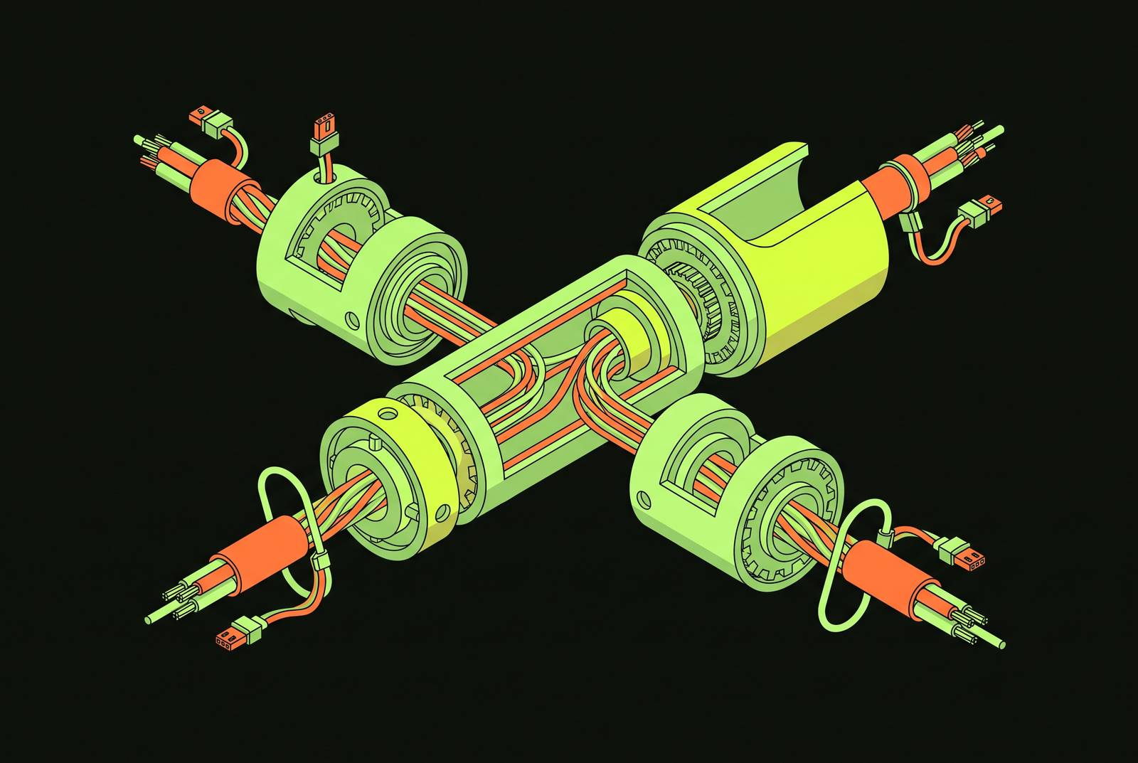
The wrist of a 6-DOF robot arm, the assembly formed by joints J4, J5, and J6, puts more mechanical stress on a cable than any other point on the machine. Three rotational axes sit close together in a small volume, and when all three move at once, a cable running through that volume doesn't just bend. It twists in multiple planes simultaneously, a corkscrewing load that has no equivalent at the base or the shoulder, where a single joint rotates largely on its own. Each wrist axis adds its own rotational demand on top of the others, and those demands combine rather than cancel out, so the cable has to absorb a compound motion rather than a simple one.
Space works against the cable too. The wrist sits at the far end of the arm, the narrowest section of the whole structure, and that leaves little room for the kind of generous service loop or wide bend radius that would let a cable flex without stressing. At the shoulder, a designer can often route a cable along a wide arc with plenty of slack. At the wrist, the cable has to make that same directional change in a fraction of the space, which forces tighter bends and less margin for error. The combination of compound torsion and tight geometry is what sets the wrist apart from every other segment of the arm, and it's the condition every routing strategy discussed in this piece has to answer for.
Wrist cable failure modes over time
The stresses described above don't cause random failures. They produce a small set of well-understood failure modes, each tied directly to how the cable is routed.
Corkscrewing happens when a routing path gives the cable no way to release torsional buildup, which is common in dress packs bolted to wrist axes without any swivel mechanism. Over repeated cycles the cable winds tighter on itself, and that winding eats into the cable's effective service loop near the tool, leaving less slack to work with every time the wrist turns.
Fatigue failure starts inside the cable, long before you can see anything from outside. Repeated mechanical stress breaks conductor strands one at a time, and a cable can look completely intact on the outside while producing intermittent electrical faults as the damage spreads internally. Fatigue damage of this kind is invisible from outside the cable, so an arm can keep running, apparently normal, while the wiring inside is already failing until the faults spread far enough to appear in production.
Bend-radius violation comes from routing geometry that forces a cable through an angle sharper than it was built to handle, whether that's a rigid conduit or a tight corner in the wrist path. Every time the cable moves through that angle, stress concentrates at the same point, and the friction generated there produces heat that degrades both the insulation and the conductors underneath it.
High-speed applications add a fourth layer on top of the first three. Rapid acceleration and deceleration generate inertial loading right at the transition points, the wrist axes among them, which compounds torsion, fatigue, and bend-radius stress all at once rather than introducing a separate problem. None of this is accidental. These are the direct, foreseeable consequences of specific routing decisions, and the two dominant routing philosophies in use today exist largely because engineers have tried to design around exactly these failure modes.
Two routing philosophies and their tradeoffs
Every approach to wrist cable routing comes down to one of two basic strategies, and picking one doesn't eliminate the wrist's problems so much as decide which problems the design will have to live with.
The first strategy is the external dress pack: a defined, repeatable path strapped to the outside of the arm that guides and protects cables along every moving axis. Because it runs outside the arm's structure, a dress pack can often maintain a wider bending radius than an internal passage allows, which matters for cables or hoses with strict minimum bend requirements. The cost of that flexibility is exposure. A dress pack sits in the open, vulnerable to heat, weld spatter, and snagging, and unless the design includes swivel mechanisms at each axis, it still takes on the full torsional and whiplash forces generated by wrist motion, the same forces described in the section above.
The second strategy is internal hollow-shaft routing, which threads service lines through hollow structural members and hollow-shaft actuators at each wrist joint. This keeps cables shielded from outside mechanical and environmental hazards, and it removes almost all whiplash motion. Research on hollow-shaft robot design (Nguyen et al., 2024) notes that ease of cable routing was at least part of the motivation for building robots with hollow shafts in the first place, because the open shaft lets cables pass straight through rather than around. But hollow-shaft routing carries its own cost. To get a usable reduction ratio, the hollow shaft in a conventional robot usually sits at the input or intermediate stage of the transmission, and cables running through it have to survive relatively high rotation speeds without damage. A hollow shaft strong enough to meet those requirements, and wide enough to carry more cables, tends to grow in volume, which makes the robot larger overall. The bend radius available inside that internal passage can also end up tighter than a cable's rated minimum, pneumatic tubing especially, so the protection gained by moving the cable inside the structure can be partly canceled out by the sharper geometry the cable has to bend through.
Neither approach solves the wrist's problem completely. One keeps bend radius generous at the cost of exposure; the other eliminates exposure at the cost of tighter internal geometry and added bulk.
Limits of standard approaches revealed by remote-actuation wrist designs
A third architecture moves the motors that drive the wrist axes away from the wrist and to the base, avoiding the need to manage cables at the wrist itself. Research on hollow-shaft robots (Nguyen et al., 2024) describes a 6-DOF arm in which the three motors driving the three wrist degrees of freedom sit at the shoulder base instead of at the wrist itself. The payoff is a cable-actuated wrist that weighs just 0.8 kg, which improves safety during human interaction and cuts the torque the elbow and shoulder motors need to produce. The D3-ARM, described in 2025 research, pushes the same idea further: every electrical component sits at the base, and the arm's 776 mm moving section delivers six degrees of freedom at a total moving weight of 1.6 kg.
Moving the motors solves the wrist's torsion and bend-radius problems, but relocating them away from the wrist doesn't make the cable tension and torque transmission problem disappear. It relocates it. When a proximal joint, closer to the base, rotates, the length of cable needed to drive a distal joint farther out changes with it. That shift causes the cable to lose tension and transmit torque inaccurately at the wrist, a motion-coupling problem that neither dress packs nor hollow-shaft routing ever has to contend with in the same form, because in both of those designs the motor and the joint it drives stay in a fixed relationship to each other.
A second, narrower problem occurs specifically at antagonistic cable pairs on the yaw joint, where two cables pulling against each other can twist together and rub, wearing each other down in a way that has nothing to do with the torsion or bend-radius failures described earlier. Remote actuation, in other words, trades the wrist's local mechanical stresses for a long-path coupling problem that has to be solved somewhere else in the system, and that trade is the subject of the next section.
Mechanical versus software decoupling as the central design decision in cable-driven wrists
Once motion coupling is accepted as the price of moving motors away from the wrist, engineers face a genuine fork in how to correct for it: solve the problem with mechanical geometry, or solve it with control software. Neither answer has won out, and researchers are still weighing the consequences for weight, speed, and overall complexity against each other.
The mechanical route builds the correction into the arm's structure. The D3-ARM uses a low-friction motion decoupling mechanism positioned at the proximal joints, Joint1, Joint2, and Joint3, to keep cables aligned and transmit motor power efficiently, achieving full joint decoupling while keeping every electrical component at the base; a cable-pretension mechanism works alongside it to keep tension stable across the long transmission path. This isn't a new idea so much as a refinement of one. The LIMS arm, cited in the D3-ARM research, used a rolling joint at the elbow specifically to decouple elbow motion from wrist tendon movement, an earlier version of the same mechanical philosophy. Research on bionic wrist design (He et al., Biomimetics, 2025) cites a related prior design, by Scarcia et al., that uses two hollow rotational joints with vertical axes so that finger-control tendons can pass through without interference; He et al.'s own wrist instead uses a tendon-driven bionic spherical joint driven by two pairs of cables that mimic antagonist muscle pairs, a structural answer to the same routing-and-coupling problem in a two-degree-of-freedom wrist. The objection to all of these mechanical solutions is straightforward: pulleys, rolling joints, and alignment mechanisms add mass and complexity, and that added weight can cancel out some of the savings that motivated remote actuation.
The alternative is to leave the geometry simple and correct cable length changes through control algorithms instead. The D3-ARM research describes a system called the CDSSR, which achieves full-joint decoupling using a cable length compensator built into each articulation. But that approach comes with a documented cost: compensation-based decoupling hurts cable tension stability, which puts a ceiling on how fast and how precisely the joint can move. Software decoupling keeps the arm lighter and the mechanism simpler, but it limits dynamic performance in a way the mechanical approach does not. Neither side has made the other obsolete, and the choice between them shapes everything downstream, from how fast the arm can move to how much it ends up weighing.
How application context determines which routing strategy is appropriate
None of the strategies above is correct in the abstract. Each one is correct for a specific environment, and the right choice depends on what the arm has to do, what it's carrying, and what kind of lines it needs to route.
In industrial welding and high-throughput manufacturing, hollow-wrist routing tends to win out. Running cables and hoses internally shields the dress package from mechanical interference and stops the whiplash motion that external routing is prone to, and a torch cable routed internally moves more smoothly as a result, the logic behind the FANUC ARC Mate 120iD's hollow wrist design. External dress packs, by contrast, sit directly in the path of weld spatter and repeated heat cycles, and a clean internal path also tends to pair more easily with tool changers built for hollow-wrist robots.
In collaborative robots that work near people, the case for remote actuation gets stronger. The hollow-shaft research cited above shows that a 0.8 kg wrist, achieved by moving the motors to the base, directly lowers injury risk during human interaction and reduces the torque demand on the elbow and shoulder motors, a combined safety and energy argument for keeping mass away from the distal end of the arm. In this setting, how easy a dress pack is to maintain matters less than how little inertia and mass sit near the person working alongside the robot.
In radiation zones, underwater environments, and other hostile settings, centralizing components at the base is a requirement, not merely a design preference. The D3-ARM research notes that protecting motors centrally is necessary for durability in high-radiation and underwater tasks, which pushes every cable in the arm back toward the base whether or not that's the most efficient routing choice otherwise. In these environments, the friction and coupling costs of a long cable path are accepted outright, because the alternative is exposing electronics that can't easily be replaced.
In surgical and minimal-access robotics, space constraints override every other consideration. The CT-guided needle insertion system described by Zhang et al. (2025) mounts a 5-DOF cable-driven end-effector onto a 6-DOF robotic base so it can operate inside the confined bore of a CT scanner, an environment where an external dress pack simply has nowhere to go. Here, precision and compactness take priority, since surgical cable systems are typically replaced or overhauled on a schedule tied to procedures rather than to elapsed time.
Across all four settings, one type of line resists both major philosophies more than any other: pneumatic tubing, whose minimum bend radius is often tighter than what either a dress pack's external path or a hollow shaft's internal passage can comfortably provide. That constraint carries directly into how a routing strategy has to be executed once it's chosen.
Practical decisions that determine whether a chosen routing strategy holds up in service
Picking the right routing philosophy only gets a design halfway there. Whether that design actually reaches its rated service life comes down to execution details: pretension, strain relief, swivel placement, and the construction of the cable tightener itself.
Cable slack is a distinct failure mode in its own right, separate from torsion and bend-radius damage, and it has to be designed against from the start rather than patched later in software. The D3-ARM integrates a cable-pretension mechanism specifically to keep long-distance cable transmission stable, so slack prevention works as a structural requirement rather than an afterthought.
Strain relief at the cable's locking end matters just as much. Research on hollow-shaft robot design (Nguyen et al., 2024) describes a cable tightener built to do two things at once: tighten the cable conveniently and reduce the stress concentration that builds up near the locking end, which is what causes cables to loosen over time. Under an initial tension load, the 2024 study found that design held onto most of its tension even after an extended period at room temperature. Without that kind of strain relief, a cable tends to shift back and forth inside the dress pack with every cycle, which gradually shortens the service loop near the tool and eventually causes the connector itself to fail, a mechanical problem that no amount of software compensation can fix after the fact.
Where external dress packs are the chosen strategy, torsion distribution becomes the deciding factor in service life. Chain links built with a torsion stop spread rotational stress evenly across the full length of the chain instead of letting it concentrate at a single wrist axis, and that distribution is what extends the cable's working life under repeated motion. The wrist will always be the harshest cable environment on the arm. Whether a given design survives it depends less on which philosophy was chosen than on whether these specific details, pretension, strain relief, and torsion distribution, were engineered in from the start.
Sources
- Low-Cost Cable-Driven Robot Arm with Low-Inertia Movement and Long-Term Cable Durability
- Development of a Cable-Driven Bionic Spherical Joint for a Robot Wrist - PubMed
- D3-ARM: High-Dynamic, Dexterous and Fully Decoupled Cable-driven Robotic Arm
- Dexterous Control of an 11-DOF Redundant Robot for CT-Guided Needle Insertion With Task-Oriented Weighted Policies
- D3-ARM: High-Dynamic, Dexterous and Fully Decoupled Cable-driven Robotic Arm
- Streamlined multi-axis robot wrist assembly with partially enclosed hydraulic and electrical lines to minimize the wrist envelope
- How Faster Robot Cycle Times Increase Cable Wear and Downtime
- Why Robot Cables Fail in High-Complexity Motion Applications