Collaborative Robot Force Limiting Hardware Under ISO TS 15066
Compliance testing for power-and-force-limiting hardware is now mandatory, not optional.
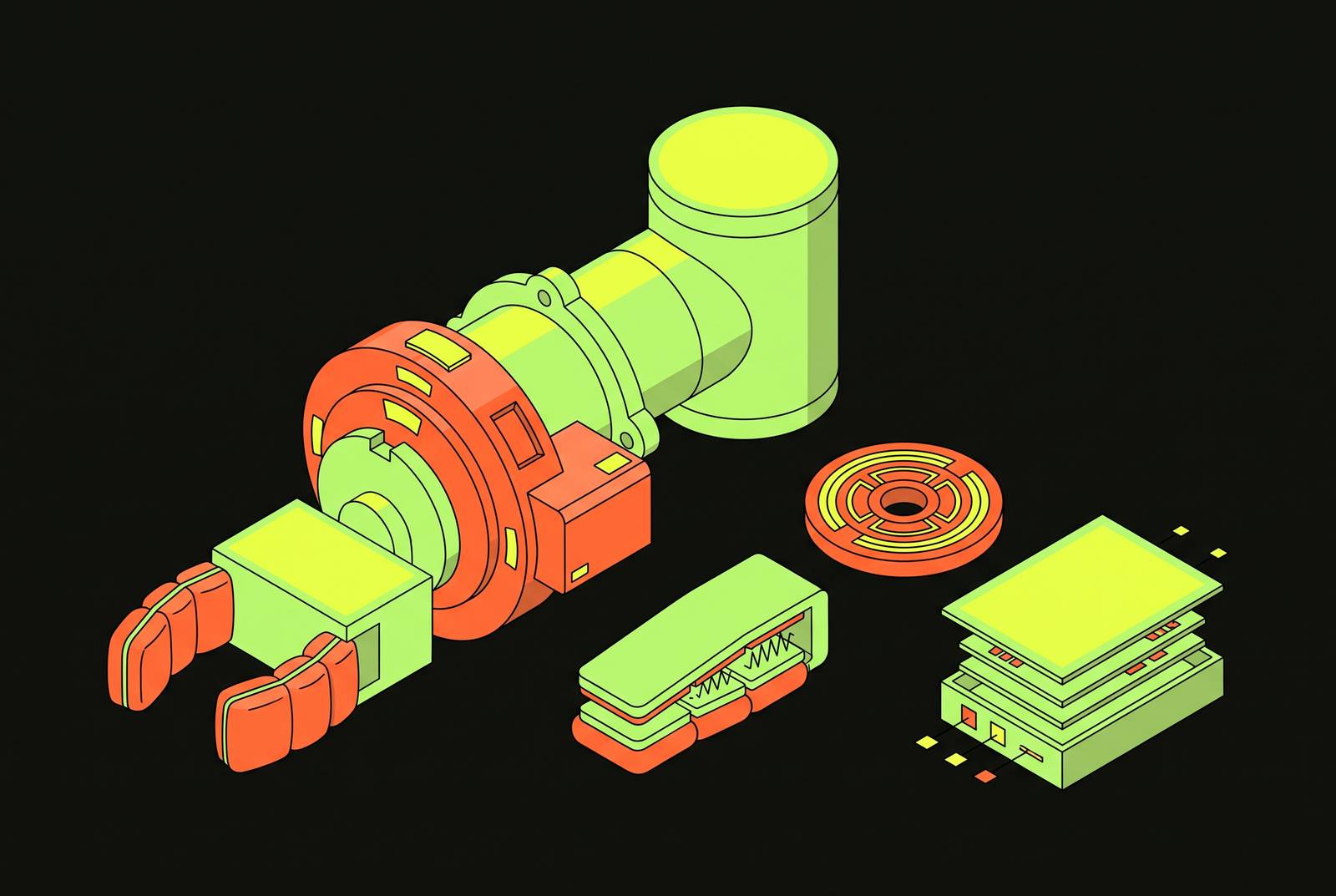
Power-and-force-limiting hardware doesn't get a pass just because the robot arm underneath it carries a safety certification. ISO/TS 15066's biomechanical thresholds only mean something once someone translates them into the mechanics of a specific gripper, a specific skin, and a control loop watching for contact. That translation is where compliant deployments and merely convincing-looking ones part ways.
ISO/TS 15066:2016 doesn't exist anymore as its own document. Its requirements for power and force limiting, along with the rest of its collaborative-application guidance, got folded into ISO 10218-2:2025, merging the two documents into one standard. That's a change in where the rules live. The rules themselves stayed the same.
The four recognized collaborative techniques haven't moved: power and force limiting, hand guiding, speed and separation monitoring, and monitored standstill. What changed is that they now sit inside ISO 10218 itself instead of being cross-referenced out to a supplemental technical specification that manufacturers could treat as advisory. In the US, ANSI/A3 R15.06-2025 landed in September and October of 2025, replacing the 2012 version and renaming "safety-rated monitored stop" to "monitored standstill" to match the international language.
For anyone building or integrating a cobot cell, PFL compliance testing now sits inside Part 2 as a mandatory requirement. Nothing about the pain-threshold data or the pressure limits changed. What changed is how much room an integrator has to treat those numbers as optional, and the answer now is none.
PFL hardware requirements: force, pressure, contact type, and body region
PFL rests on a simple premise: a moving robot can touch a person, on purpose or by accident, as long as the contact stays under the pressure and force where injury or pain starts. Those limits come from pain-onset research, and the standard draws its line well before tissue damage becomes likely, a more conservative bar than "don't cause harm."
The numbers trace back to a study at the University of Mainz, which tested 100 subjects across 29 body regions and produced the pressure and force values tabulated in the standard. Those figures are what PFL hardware has to respect, region by region. A fingertip tolerates a very different pressure than a thigh or a torso.
Two variables decide which number applies. The first is contact type. Contact geometry determines which permissible force and pressure value applies, with broader, more distributed contact shapes receiving higher limits than concentrated ones. Sharp contact shapes are banned outright on a cobot's exterior, no exceptions, a design prohibition baked directly into the standard.
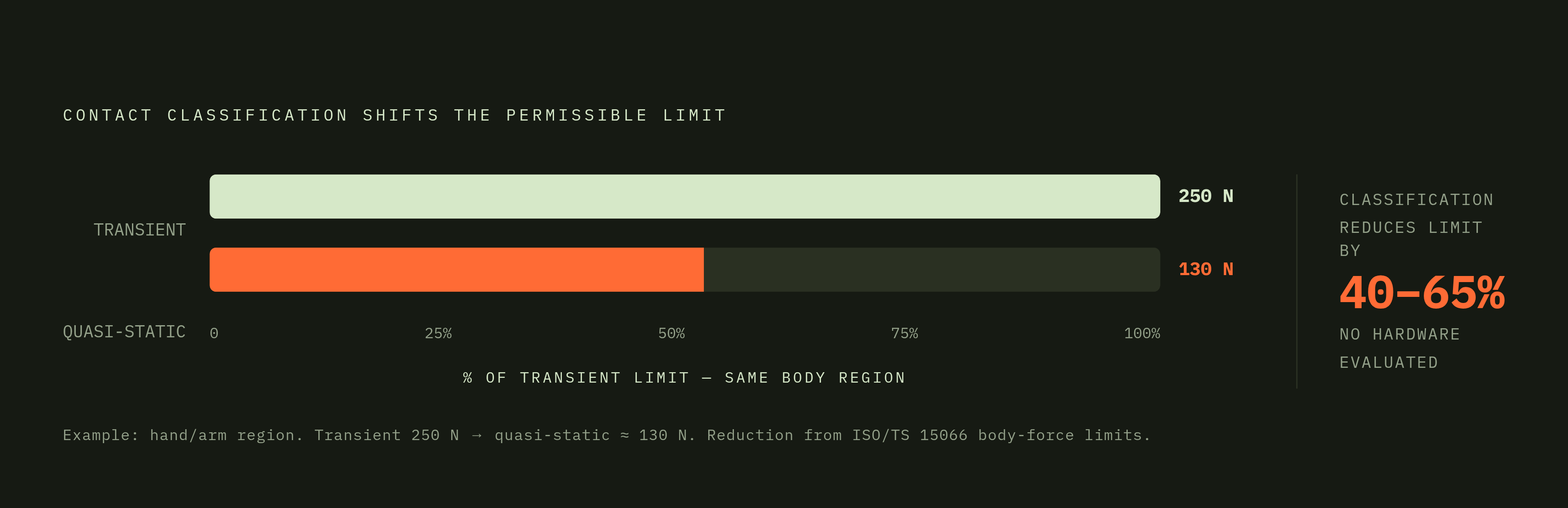
The second variable is load type, and it's where a lot of PFL programs go wrong without noticing. Transient contact, a brief impact before any safety function has time to react, gets a higher permissible value because the injury mechanism is a short spike, not sustained compression. Quasi-static contact, the clamping scenario where a person gets trapped between the robot and a fixture and force keeps building, gets thresholds roughly 40 to 65 percent lower than the transient values. Sustained compression damages tissue at forces a brief impact tolerates fine. A gripper or tool that passes a transient impact test can still fail badly in a clamping scenario. The two require separate validation, not one test standing in for the other. The standard addresses exactly that substitution, and engineers still make it anyway, often without realizing which test they skipped.
Ambiguity in risk assessments created by the standard's contact-classification language
Researchers at the Technical University of Munich, Kirschner and colleagues, tested four commercial collaborative robots (a KUKA LWR iiwa 14, a TM5 700, a UR10e, and an FE robot) and found that the technical specification's own contact-scenario definitions contradict each other in places, producing inconsistent readings depending on who applies them.
The ambiguity doesn't live in the limit values. Annex A's numbers are fixed. It lives in classification: whether a given real-world contact counts as transient or quasi-static, constrained or unconstrained. Since quasi-static thresholds typically run at only 40 to 65 percent of the transient values, the classification call decides the outcome before any number gets applied. Two engineers looking at the same physical setup, a gripper reaching into a fixture, say, can walk away with different contact-type conclusions and therefore different permissible speeds and forces for the exact same robot doing the exact same task. That's a real gap in the standard's current language, not a minor wording issue, and no integrator should mistake it for one.
Kirschner's team proposes a decision tree paired with constrained collision force maps, tools meant to remove the guesswork from classification. Neither has made it into the standard yet. Until one does, the burden sits with each integrator's own risk assessment process, and that process is only as good as the judgment behind it. The standard is not self-executing here. Someone still has to make the classification call, and the standard does not make that call for them.
The three hardware approaches to sensing and limiting contact force
Most cobots on the market combine more than one sensing method, and the combination chosen determines which contact scenarios the cell can actually catch within the biomechanical limits it's supposed to respect.
Joint torque sensing and motor-current estimation form the baseline approach, and it's the weakest of the three for fine work even though it's the most common. The controller holds an expected torque profile for whatever path it's running at whatever speed it's running, and when measured torque deviates past a threshold, it triggers a protective stop. Common sensing elements include force/torque sensors, current sensors in the joint servo drivers, and dedicated torque sensors in the actuators themselves. Current estimation alone works fine for coarse tasks, but it struggles once forces get subtle, contact direction changes fast, or the task calls for real compliance. High-sensitivity joint torque sensors close that gap by letting the controller see torque spikes directly instead of inferring them from current draw, which speeds up detection and improves accuracy, particularly on small-payload cobots where current-based estimation is weakest to begin with.
Sensorless, observer-based approaches come into play when torque sensing isn't available at every joint. These energy-based methods try to limit the robot's overall mechanical energy rather than tracking force directly at the contact point. It's a workable fallback for retrofits or older robot platforms that were never built with full joint instrumentation, but it adds a layer of inference between the actual physical contact and the safety response firing because of it, and that inference gap is why it should stay a fallback rather than a first choice.
Adaptive, effective-mass-based collision sensitivity is the newer approach, and it solves a specific inefficiency: fixed-threshold systems stop the robot even when the impact force is well within biomechanical limits, costing cycle time for no safety benefit. The effective-mass framework computes an estimated collision force for each robot body segment individually, in real time, and only interrupts motion when that segment's estimated force would actually cross the limit. Research in this area has involved a UR10e fitted with AIRSKIN for collision detection and isolation. The intelligence sits in how the controller maps the robot's live configuration to the correct body-region limit.
Compliant robotic skins and their effect on the physical contact event before sensing begins
Skin changes the physics of the collision before any sensor has to interpret it. Research comparing impacts on robotic manipulators with and without protective skin shows that soft skins cut peak impact force and stretch out the collision duration. A longer, softer impulse is mechanically gentler than a sharp spike carrying the same total energy, and that lines up directly with the transient contact limits in Annex A.
AIRSKIN, a commercial pneumatic skin certified to PLe/Category 3, is the clearest example of this idea built into hardware. It's a pressure-sensitive covering made of modular pads at varying thickness, and that thickness is a passive protection variable an integrator can tune to the contact geometry of a given application. Each pad houses a sensor and maintains a slight internal air overpressure. Up to 15 pads chain together and connect through two OSSD safety outputs straight into the robot controller's safety inputs. The safety function runs on continuous pad diagnostics: if pressure drops in any pad, it triggers a safe stop, and the pneumatic compliance of the pad itself is damping the mechanical force on the way down at the same time. AIRSKIN carries CE marking and certification from TÜV Austria and TÜV Rheinland, and it's the same skin used in the UR10e study above, where it supported collision detection and isolation alongside its cushioning function.
SkinAxis, a research design rather than a shipping product, targets a specific gap in that space. Most soft skins on the market get optimized for either compliance or sensing, rarely both at once. SkinAxis tries to jointly optimize quasi-static touch sensitivity and impact safety in one material design, embedding a compact 3D force sensor inside soft material so the skin can localize touch, not just cushion it. What sets the research apart is process: the design gets guided by a quantitative trade-off analysis between touch sensitivity and impact mitigation, tested systematically against ISO/TS 15066's limits, and the paper behind it names the absence of that kind of testing discipline as a real gap in prior skin research. It's not commercial yet, but it points at where the field is headed: skin validated against the standard's numbers directly, not bolted on and assumed safe.
The design implication runs deeper than picking a comfortable material. A sufficiently compliant skin can shift a contact event's classification from semi-sharp toward blunt, which changes which Annex A limit applies to it. Skin selection belongs inside the contact-type analysis itself, not bolted on after the classification has already been decided.
Robot certification versus cell certification: validating PFL with physical measurement devices
A robot arm's certification covers the robot arm. It doesn't cover the finished cell, and treating it as though it does is one of the more common ways PFL programs fail quietly. Measurement has to happen at the actual end effector, on the actual workpiece, at the real operating speed, inside the real cell layout. Validating PFL is a physical measurement exercise, not a paperwork exercise, and no amount of robot-level certification substitutes for it.
The device doing that measurement has to simulate human tissue, reproducing the stiffness and damping of the specific body region under evaluation. The Pilz Robot Measurement System (PRMS) does this with nine springs of different force constants standing in for different body regions' mechanical response, pressure-indicating films that measure local pressure against the standard's body-region limits, and compression elements designed to reproduce the mechanical response of human tissue. The package is designed to evaluate the resulting force and pressure readings against the standard's body-region limits.
A separate device, the CoboSafe CBSF-75 from GTE Industrieelektronik, shows up in a published study that measured 60 impacts on a real robot arm running at 400 mm/s. The quasi-static contact force limit under ISO 10218-2:2025 for that scenario is 140 N. The average measured force across those 60 impacts came out to 98 ± 44 N. Real-world contact force swings widely even under controlled, repeated conditions on the same setup. One measurement, or even a handful, doesn't characterize a cell. Sixty did, and the spread they revealed is why the standard calls for physical testing rather than a calculated estimate.
Putting the translation into practice: what a genuinely compliant PFL deployment looks like versus one that only appears compliant
The failure pattern that only looks compliant has a consistent shape. The robot arm carries its certification, a speed limit sits programmed into the cell, and everything on paper checks out. But that speed limit came from the robot's rated payload and a generic assumption about which body region might get hit, standing in for an actual contact-type classification of the real end effector against the real body regions a person could reach inside the real cell layout. A plausible-looking number stands in for an analysis that never happened, and that substitution is the single most common way these programs fail, usually without anyone noticing until an incident forces the question.
Genuine compliance runs the translation in order, and skipping a step breaks the chain. Risk assessment comes first: identify which body regions a person can actually reach and under what contact geometry, since that decision determines which Annex A limits apply and requires validating transient contact, quasi-static contact, or both. From there, hardware selection (sensing method, skin, joint instrumentation) has to answer to that classification rather than set it. Validation then has to happen with a physical measurement device on the finished cell, at operating speed, because a robot's factory certification was never built to answer for the tool, the fixture, or the layout bolted onto it afterward.
Each step depends on the one before it holding up. A risk assessment built on the wrong contact-type call produces a speed limit that's wrong in the same direction, no matter how well-instrumented the robot underneath it happens to be. The hardware can only be as compliant as the classification that told it what to defend against, and no amount of certification paperwork changes that fact.
Sources
- Collaborative robot safety standards you must know - Standard Bots
- Tech Papers: ISO/TS 15066 Explained | Robotiq
- A Statistical Model to Determine Biomechanical Limits for Physically Safe Interactions With Collaborative Robots
- Control Design for Safe Human-Robot Collaboration based on ISO/TS 15066 with Power and Force Limit
- Example Application of ISO/TS 15066 to a Collaborative Assembly Scenario
- researchgate.net
- ISO 10218 & R15.06-2025: What Changed for Cobot Safety
- arxiv.org