FEA-Driven Weight Reduction in Robot Link Design
Finite element analysis cuts robot weight while preserving stiffness and speed.
Cutting mass from a robot link changes the torque every upstream actuator has to produce, not just the number on a spec sheet. Lighter links lower the moment of inertia at each joint, which lowers the torque needed to move them, which in turn lets engineers use smaller and cheaper actuators, or push the same actuators to move faster or carry more payload. For battery-powered and mobile platforms, that lower actuator demand stretches operating time between charges. Sha and colleagues, writing in SAGE in 2020, point to exactly this effect in a humanoid robot: topology optimization cut frame mass by 50.15%, citing work by Ye and colleagues, without any loss in stiffness or vibration performance, and the authors connect that mass cut directly to longer battery life.
Stiffness and mass usually move in opposite directions. Traditional metal designs get their stiffness from having plenty of material in place, so pushing stiffness up tends to push mass up with it. Cutting material from a load-bearing link by trial and error, without knowing how stress actually moves through the part, risks a failure nobody predicted; leaving material in "to be safe" just wastes the weight the effort was meant to remove. Finite element analysis exists to settle that argument before a single part gets machined: it shows the stress and deformation field inside the link first, so any material removed comes from places that can actually spare it. That is what makes FEA the starting point for a repeatable weight-reduction process rather than a one-off guess.
The three-stage FEA pipeline
FEA-driven weight reduction runs through three stages, pre-processing, solving, and post-processing, and each stage only works because of what came before it.
Pre-processing sets up the problem: the link's geometry gets imported or built in CAD, a mesh gets generated (the element type and density chosen here set the ceiling on how accurate the whole analysis can be), material properties get assigned, boundary conditions get defined at fixed supports and joint interfaces, and loads, forces, torques, gravity, inertial effects, get applied. Every one of those choices is an assumption standing in for reality, and none matters more than whether the loads reflect how the link actually gets used in service (a point sharp enough to need its own section later). One pre-processing decision carries particular weight: whether to model the link on its own or inside the full robot assembly. A 2026 preprint on expected strain energy frameworks found that optimizing a part in isolation produces stress and deformation patterns that differ from those measured once the part sits inside the assembled system, a mismatch traceable to Saint-Venant's principle, and that gap cuts into how much a lightweight redesign actually delivers.
Solving is where the computation happens. The solver calculates nodal displacements across the mesh, then works out stress and strain from those displacements. For cases where dynamics matter, modal analysis runs alongside the static solve, pulling out natural frequencies and mode shapes so vibration behavior can be checked at the same time as strength.
Post-processing turns the raw numbers into decisions. Stress contour maps show which regions carry heavy load and need to stay, and which are lightly loaded and become candidates for removal. Factor-of-safety maps confirm how much margin exists against yield or fracture, and displacement maps flag anywhere the design is too flexible. This output becomes the direct input to topology optimization: it hands the optimizer a specific, mapped list of where material can safely come out.
Topology optimization translates post-processing output into a new geometry
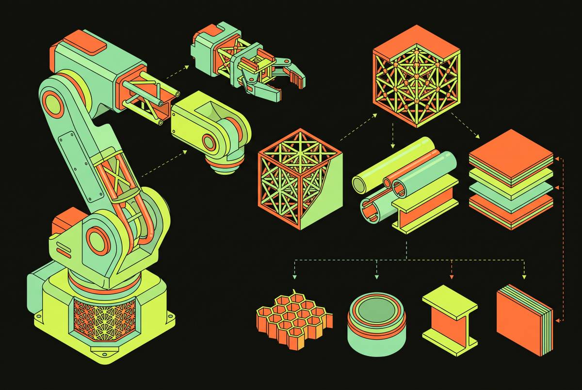
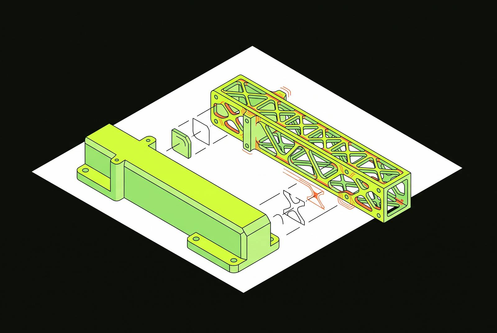
Topology optimization takes the stress map from post-processing and turns it into a material-distribution problem. Material comes out of low-stress regions while the load paths connecting supports to applied forces stay intact, all within constraints set for stiffness, strength, and what can actually be manufactured. The optimizer works iteratively, shifting material density across the mesh step by step until it minimizes an objective, usually compliance (maximizing stiffness for a given mass), while staying inside volume or stress limits set at the start. Left to run, this process tends to produce lattice structures on its own: material concentrates along the paths that actually carry stress, which is a far more efficient use of mass than a solid block.
The scale of what this delivers varies by application, and the published cases make that range visible rather than pointing to one "correct" outcome. In a six-axis serial robot's upper arm, topology optimization cut the arm's mass substantially and raised the first- and second-order natural frequencies of the whole machine at the same time, a result reported at ACM/CMSDA in 2025. In the humanoid robot frame cited earlier, the reduction ran past half the original mass with stiffness and vibration performance held steady. A lumbar rehabilitation robot's gear, optimized in OptiStruct and reported in a Springer volume in 2026, came out with a branching, dendritic geometry that removed 4.115 kg for a weight reduction ratio of 30.2%, all while still meeting its safety coefficient and deformation targets. A garbage-truck robotic arm, studied by Li and Li in Frontiers in Mechanical Engineering in 2025, saw a meaningful cut in overall mass while stress distribution still met strength and stiffness requirements, and the minimum factor of safety across every link in the arm stayed within acceptable bounds. Posmykova and colleagues, in proceedings published by Springer in 2026, used Altair Inspire to run FEA-guided topology optimization and brought maximum displacement down from 0.14 mm to 0.06 mm while raising the factor of safety from 15 to 18. Read together, these results show that the size of the payoff depends on how aggressively the constraints get set and how much geometric freedom the application can tolerate, not on any single formula that applies everywhere.
When dynamic performance matters as much as static strength, modal analysis gets folded into the same workflow. Li and Li, drawing on an approach from Alshihabi and colleagues, describe identifying the joint carrying the highest torque first, running FEA specifically on that joint to check its vibration characteristics, and only then redesigning it through topology optimization. The six-axis arm result, where natural frequency went up alongside mass going down, makes the reason for this sequencing concrete: a link that gets lighter but also loses stiffness can end up exciting resonance at the speeds it actually operates at, which defeats the purpose of lightweighting in the first place.
Material selection interacts with the topology result and introduces its own trade-offs
The topology result only tells half the story. It shows where material can go; the material assigned to that shape determines how much of the theoretical weight saving is actually usable, and the same stress map that guided the geometry also limits which materials qualify. A material that saves weight but cannot clear the factor-of-safety threshold the FEA already established is not a substitution worth making, regardless of how attractive its density looks on paper.
Swapping metal for composite is the most common way engineers try to capture more of that saving. Carbon fiber-reinforced polymer offers a stiffness-to-weight ratio and vibrational stability that make it a stronger fit than steel or aluminum alloy for robotic arm links, especially where damping vibration matters as much as carrying load. That advantage comes with a modeling cost: CFRP is anisotropic, meaning its mechanical performance depends on fiber orientation, fiber volume fraction, and the sequence in which layers get stacked. An FEA model built on isotropic assumptions, the kind that treats the material as uniform in every direction, will produce results that look clean but do not match how the part actually behaves. Cost is the other constraint on CFRP: it prices out of some applications. Glass fiber-reinforced polymer has been put forward as an alternative that gets close to CFRP's stiffness and damping properties at a lower price point.
Polymers and engineering plastics show a different kind of advantage, one that is visible clearly at the scale of a single component. The lumbar robot gear study mentioned earlier compared five materials directly: Steel (AISI 1015), Steel (C45E), Titanium (Ti-17), ABS, and PEEK. PEEK came out at an optimized mass of 1.597 kg with a minimum factor of safety of 2.8; ABS landed at a lower mass still but with a minimum factor of safety of only 1.12. Titanium (Ti-17) delivered the lightest mass among the metal options at 6.205 kg but at the highest cost, illustrating that material selection involves a cost-performance frontier rather than a single optimum. Both plastics beat every metal option on mass by a wide margin, and PEEK's safety factor ran 2.5 times higher than ABS's. PEEK was the material chosen for the gear despite its higher cost.
Manufacturing process narrows the choice further. For a smart-manufacturing effector arm, Posmykova and colleagues chose AlSi10Mg alloy specifically because it offered a favorable weight-to-cost ratio and could be built with Selective Laser Melting, a reminder that the material list available for a given link is bounded by what the intended manufacturing process can actually produce. Fatigue deserves more attention than it typically gets in these material swaps: rotary joints in particular see severe, repeated loading over their service life, and a topology optimization that only checks static strength without accounting for fatigue life is leaving a real failure mode unexamined.
Working-condition definition as the most consequential assumption in the pipeline
Everything downstream, the topology result, the material choice, the factor-of-safety numbers, rests on one earlier decision: whether the loads defined in pre-processing actually represent the worst conditions the link will face once it is in service. Get that wrong, and the solver still runs, the post-processor still produces clean-looking stress maps, and the optimizer still removes material with total confidence, all based on a load case that never happens in the real robot.
The common shortcut is to pick one extreme working pose, treat it as the worst case, and run the whole analysis against it. That simplification can quietly build in boundary conditions that are not actually conservative. Collaborative robots move through multiple joints changing angle at once, and the specific combination of joint angles that produces the true peak load on a given link is rarely obvious just by inspection. A single assumed pose can miss the true peak load on the link. When that happens, the load conditions feeding the optimizer diverge from the real maximum the link will see, and the optimizer removes material based on a load case that understates what the part actually needs to survive.
One response to this gap is orthogonal-experiment-based working-conditions topology optimization, known as OEWC-TO, which samples a systematic set of representative joint-angle combinations instead of betting on a single guessed worst case. That sampling produces a load envelope closer to what the link actually experiences across its full range of motion. Optimizing an assembly compounds the same problem: a link optimized on its own carries boundary conditions at its interfaces that are only approximations of what happens once it is bolted into the full robot. The 2026 strain-energy framework mentioned earlier notes that modeling the full assembly avoids the Saint-Venant deviation that occurs when a single part gets optimized in isolation. Building on that, the same preprint proposes expected strain energy across multiple working conditions as a single unified metric: strain energies get calculated across a distribution of operating poses, and the expected value across that distribution drives the optimization, rather than any one extreme case standing in for all of them. That approach gives engineers one number that tracks stiffness, vibration, and mass together, instead of checking each separately against a pose that may not be the real worst case.
Multi-load, time-varying, and additive-manufacturing advances in the pipeline
Three developments from 2025 and 2026 push the pipeline past what static, single-pose, isotropic FEA could handle on its own.
The first addresses motion directly. A design-dependent topology optimization framework for multi-component robotic arms uses the Bi-directional Evolutionary Structural Optimization method, known as BESO, to bring self-weight and inertial loads into the optimization while accounting for the time-varying acceleration a serial arm experiences as it moves through a trajectory. That replaces the older assumption of one static pose with an optimization that tracks how loading actually changes as the arm accelerates and decelerates through its motion.
The second joins material selection to manufacturing method. An integrated lightweighting strategy published in March 2026 combines material selection, structural design, and additive manufacturing specifically for CFRP service robot structures. Fused deposition modeling with continuous-fiber reinforcement gets around the geometric limits that traditional molding imposes on composite parts. Topology-optimized shapes that would have been impossible to manufacture before can now get built as organically shaped, FEA-informed links. In a mobile robotic system studied under this approach, the optimized components were manufactured using FDM with ABS material, and a custom power analysis tool compared energy use between the optimized and original designs, confirming that the mass reduction translated into a real system-level benefit rather than a paper improvement.
The third folds back into working-condition definition from the previous section. The same 2026 preprint that proposes expected strain energy as a unified metric extends the idea down to the level of individual optimization: part-level optimization under this framework can use size optimization or material optimization instead of topology optimization, calculated across expected strain energies spanning multiple working conditions. That gives engineers one consistent handle on stiffness, vibration, and mass across the full range of poses a link will actually encounter, rather than a result that only holds up under the one pose it was built to satisfy.
Sources
- Light-Weight Design and Application Analysis of Lumbar Rehabilitation Robot Gears | Springer Nature Link
- Frontiers | Finite element analysis and structural optimization design of multifunctional robotic arm for garbage truck
- Topology Optimization of the Effector Arm | Springer Nature Link
- Topology Optimization of the Upper Arm Structure for Industrial Robots | Proceedings of the 2025 5th International Conference on Computational Modeling, Simulation and Data Analysis
- Development of Topologically Optimized Mobile Robotic System with Machine Learning-Based Energy-Efficient Path Planning Structure
- Systematic Lightweight Method for Robotics Based on Strain Energy Distribution Optimization