Power Distribution Architecture for Multi-Axis Robot Arms
Efficient arms require voltage, topology, and conversion matched to each joint's unequal demands.
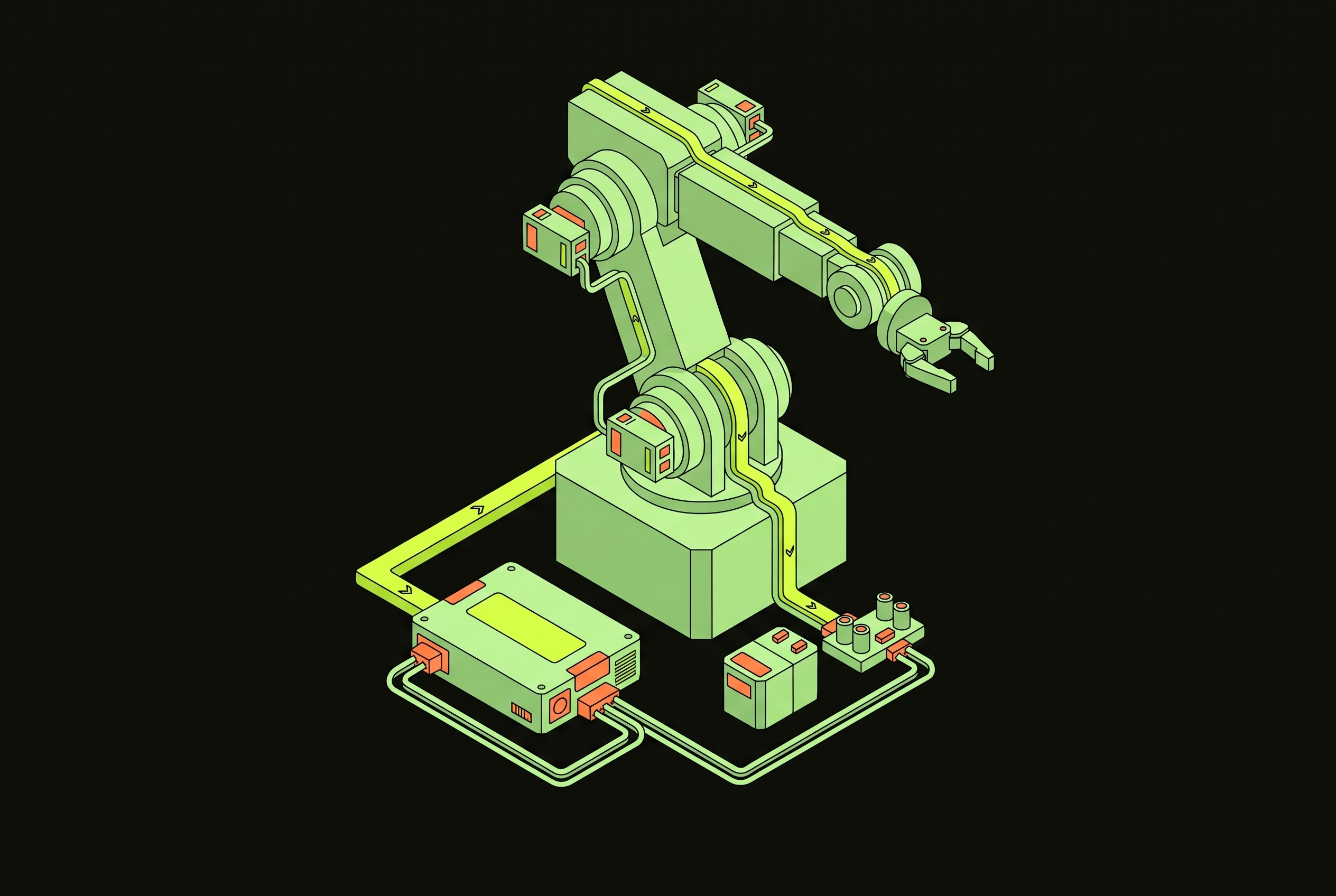
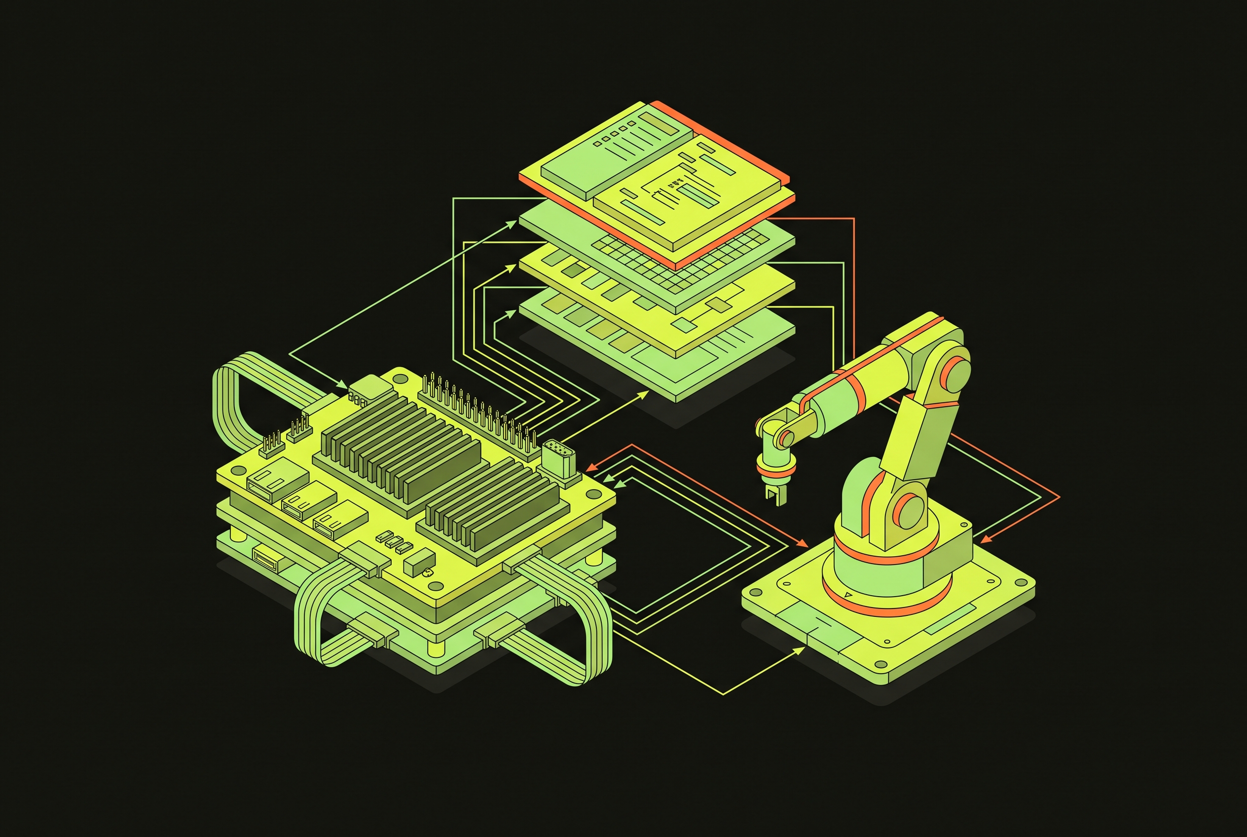
Power distribution architecture for multi-axis robot arms is a cascade of engineering choices. Bus voltage constrains distribution, distribution constrains joint-level conversion, and those choices shape control, cooling, protection, and energy recovery. A workable architecture must follow the arm’s unequal power demands rather than impose the same electrical design on every joint.
Why power architecture is the design constraint that shapes everything else in a multi-axis arm
A multi-axis robot arm is an energy-managed ecosystem. Its power architecture governs acceleration, motor-control precision, operating duration, and reliability within thermal and safety limits. These are not separate performance targets that the electrical system merely supports after the mechanical design is complete. They depend on where conversion takes place, how energy gets to each motor, and how the system handles loads as they change.
The arm’s geometry makes those dependencies unequal. In a six-axis configuration, three proximal joints control position and three distal joints control orientation, so power needs differ sharply along the arm. The shoulder and wrist thus differ in the electrical and thermal demands they place on the design and the space they have for packaging. Bus voltage, distribution topology, and point-of-load conversion must resolve those differences together, because a choice at one level restricts the options at the next.
Bus voltage selection — the first and most consequential decision in the cascade
Bus voltage establishes the electrical conditions for every downstream converter. The broader robot spectrum runs from 24 V in small cobots and wall-powered platforms, through 48–100 V packs in mid-size and delivery robots, to 750 V lithium battery systems in heavy-duty AGVs. These tiers reflect different balances of cable mass, conversion complexity, and safety classification. The voltage is therefore more than an input specification. It sets constraints on cable sizing, insulation class, connector ratings, and protection schemes before the distribution topology is fully defined.
The 48 V bus has become the main standard for humanoid and arm platforms because it cuts power loss and equipment weight while staying within the safe extra-low-voltage, or SELV, classification. That combination avoids the insulation and connector reclassification associated with moving beyond the boundary described for these platforms. The upgrade toward 72 V changes that bargain. It requires reconsidering insulation, connectors, and protection throughout the arm. Because those provisions extend into joint modules and wiring interfaces, a late voltage change reaches well beyond the main converter and contributes to design fragmentation across the industry.
The unequal power gradient across joints and why it defeats single-topology thinking
Proximal joints demand higher power than distal joints, but even that distinction is only a starting point for converter design. Acceleration and deceleration create fast current transients, while configuration and payload change the power demanded at each joint from moment to moment. The gradient moves with the arm. A converter must handle the full range of loads at its joint as well as the transient demands of the motion profile.
The actuator package further restricts the available electrical design. Brushless DC motors paired with harmonic drive or cycloidal gearboxes dominate, but the gearbox choices leave different amounts of space and thermal capacity for power electronics. Harmonic drives have high gear ratios in small packages, but cyclical loading can cause fatigue failure. Cycloidal drives offer greater durability at increased size and weight. Those mechanical tradeoffs define what can fit at the joint, so electronics packaging cannot be settled independently of actuator selection.
A design sized for proximal demand is oversized and inefficient at the wrist’s lighter loads, while one sized for distal demand is stressed by proximal peaks. Supplying each joint efficiently within its own load, space, and thermal limits makes the location and division of conversion the next architectural decision.
Centralized, distributed, and hybrid topologies — what each one actually trades away
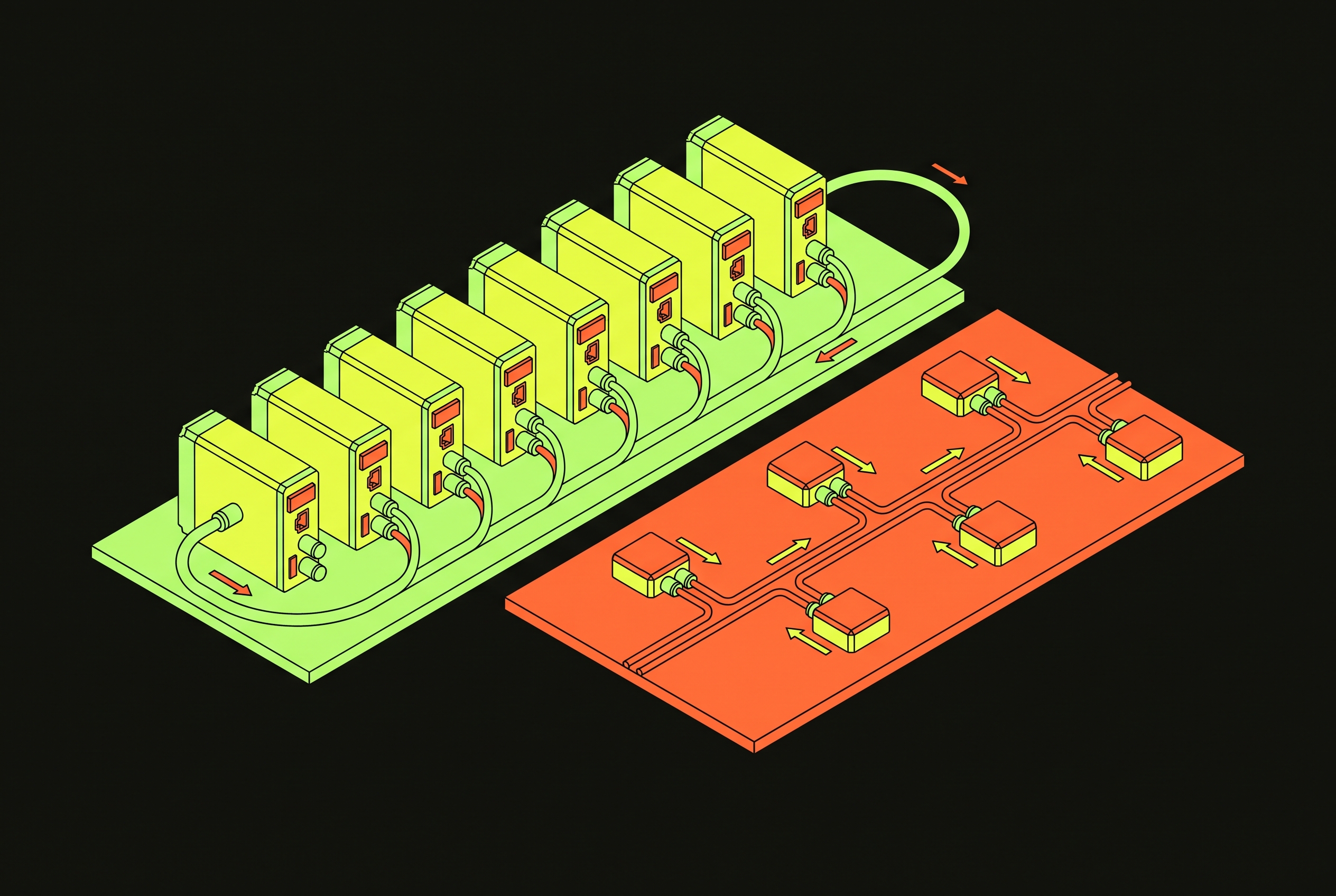
Centralized power architecture places all conversion from the input source to stable DC output at a single point. It simplifies wiring and concentrates protection logic, reducing the number of locations at which those functions must be implemented. Heat concentrates there as well. In a compact robot base, limited enclosure volume and airflow can turn that apparent simplicity into a thermal constraint.
With distributed power architecture, conversion takes place close to each load. Shorter paths from converter to load cut distribution losses and inductance, which improves dynamic response, while heat is spread across the system. Converters can also be paralleled where extra current is needed, with two buck modules sharing a joint’s load. Local flexibility has a cost. Each converter adds parts that can fail, the whole harness gets more complex, and drive electronics, connectors, and cabling add to the cost of each axis. The short local power path does not make the whole arm’s interconnection simple.
Hybrid architectures keep a main converter but share the rest of the work between intermediate and point-of-load stages. A central conversion from 48 V to 12–24 V can feed mid-power regulators for cameras, PLCs, and communication electronics, followed by miniature regulators for joint logic and sensors. The stages divide the conversion burden. Stepping down twice keeps converters at more favorable duty cycles and distributes heat without fully multiplying per-joint complexity. This approach is increasingly preferred in high-power arms, where a high-voltage DC bus or 48–72 V intermediate bus feeds smaller converters near loads.
Point-of-load conversion at the joint level — where topology meets physical reality
At each joint, the distribution scheme becomes a physical assembly with startup, protection, and packaging requirements. Inrush control and soft-start remain necessary regardless of topology, but their implementation depends on how independently drives connect to the bus. Hot-plugging makes that distinction concrete. In a multi-axis rig with hot-pluggable drives, each drive needs its own pre-charge stage, so distributed conversion also distributes a recurring cost and complexity burden.
After startup, bus-voltage and current monitoring help keep the joints protected. Digital power monitors or ADCs provide the measurements, while under-voltage lockout and over-voltage protection, including crowbars or hardware clamps, catch faults before they propagate to joint electronics. Emergency stops add a sequencing problem across axes. Brake actuation must be coordinated with shedding low-priority electronics in the correct order to avoid voltage spikes on the shared bus. These functions must fit within a joint package that also accommodates sensing and communication, making integration rather than converter efficiency alone the practical test of the topology.
Regenerative energy recovery and shared DC-bus strategies at the cell level
Regenerative braking recovers energy only when the architecture gives it somewhere useful to go. Lowering a multi-kilogram payload quickly can generate many kilowatts of back-EMF as multiple motors brake together. If that energy cannot return to a battery or the grid, braking resistors must dissipate it. The resulting heat and mass consume part of the same power and thermal budget that the distribution architecture is intended to manage.
A shared DC bus lets more than one arm take part in energy management. When multiple robot controllers are connected, an accelerating robot can use energy from a braking neighbor, which greatly cuts brake-resistor losses. Collaborative cells with coordinated motion profiles are well suited to this arrangement because robots can share energy that would otherwise stop at each controller. Dynamic power distribution for reconfigurable multi-robot organisms also demonstrates that routing can be managed across a changing network of modules.
A static cell can use one pre-charge stage on the rectifier to serve all drives, whereas a hot-pluggable drive needs its own mini pre-charge stage to avoid collapsing the bus voltage. Connection behavior therefore changes the protection design. The energy-recovery benefit cannot be separated from whether the cell has fixed connections or modules that enter and leave the network.
How GaN power stages change what is physically achievable at each joint
GaN power semiconductors ease the limits on size and heat that have held back the use of distributed electronics inside robot arms. With faster switching, the power-stage package can be smaller, so local conversion is more practical in joints with little room. A distribution scheme that looks attractive electrically still depends on whether its power stages can fit and operate within the joint’s thermal budget.
Texas Instruments demonstrated that connection at Embedded World 2026. Its GaN-based implementation increased PWM switching frequency from 20 kHz to 80 kHz, allowing electrolytic DC-link capacitors to be replaced with ceramic capacitors of equal capacitance. That substitution enabled smaller and lighter joint power stages. The demonstration used two GaN-based power boards, one driving the elbow motor and the other controlling the robotic hand’s finger joints. The split placed local power electronics at distinct points in the mechanical power gradient.
The demonstration gives a concrete example of distributed packaging. Higher switching frequency changed the capacitor implementation, while separate boards placed power control at the elbow and hand. This connects semiconductor behavior directly to the form factor required by the distribution architecture. It shows how the physical limits on per-joint electronics are being redrawn.
Per-joint intelligence and the shift from centralized DSPs to distributed control nodes
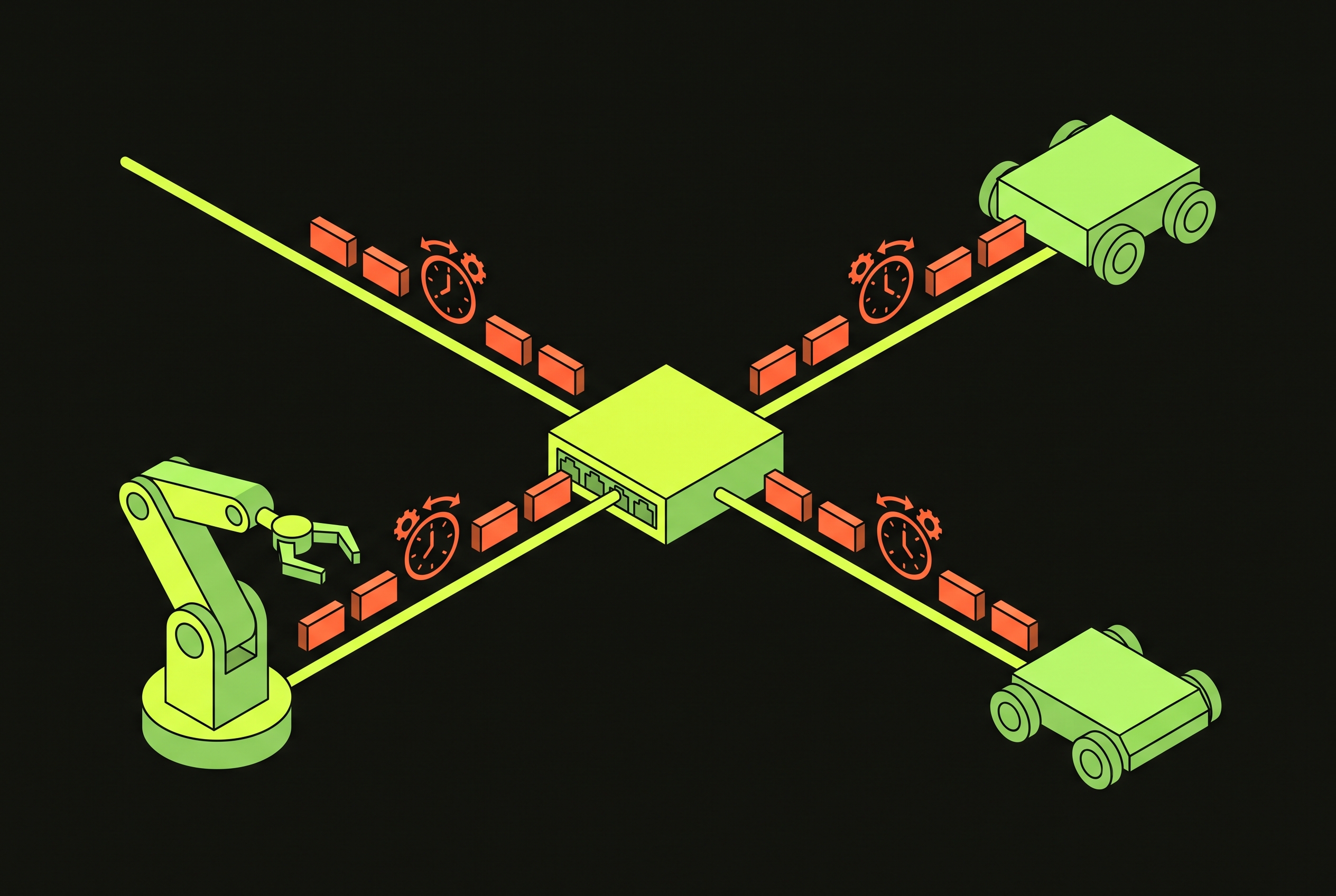
Joint boards can combine power conversion with sensing, signal digitization, and communication logic, moving the control boundary away from a central DSP toward a network of nodes. Short analog paths from encoders and current sensors can terminate at the joint board, where signals are digitized and sent upward through EtherCAT or CAN-FD. Compared with routing raw analog signals to a central controller, this increases noise immunity and reduces wire count. Distributed power therefore changes both the location of the electronics and the form of the signals traveling through the arm.
Torque, speed, and position loops can run locally at the motor controller or centrally, and the TI demonstration supports both approaches. Designers must decide how much intelligence belongs at each node and what information travels over the network, as well as how many axes a single DSP can manage. Modularity adds a maintenance consequence as well. Replacing a joint also replaces its control board, which is useful for service but requires power, sensing, and communication to form a validated, replaceable unit.
Standardization pressure and the open-platform trend that is forcing these choices into the open
Emerging formal standardization is bringing power and communication choices into a shared design space. Decisions once contained within proprietary joint modules now have implications for multi-vendor arm interoperability. Open platforms create parallel pressure from developers. Seeed Studio launched the reBot Arm B601 in April 2026 as a fully open-source six-plus-one-degree-of-freedom arm with a 1.5 kg payload for physical AI development. Its open design exposes power architecture choices to the developer community rather than leaving them hidden inside proprietary modules.
The physical layer remains an unresolved constraint. EtherCAT and CAN-FD were built for factory wiring, but modern arms need thin, lightweight connections inside them. More physical-layer options are needed before vendors can agree on a standard for distributed joint communication. The move toward 72 V also makes compatibility harder, because crossing the SELV boundary changes what is needed for insulation, connectors, and protection. Manufacturers built around 48 V SELV connector families therefore face hardware revision decisions that an interoperability standard must address.
GaN is changing how electronics fit into joints, distributed control is changing where communication takes place, and higher bus voltages are changing the interfaces that connect modules. Common interfaces can support interoperability only if they account for those linked choices. The forward-looking tension is between making modules compatible and preserving room for architectural change, turning the power-design cascade into a shared engineering negotiation.
Sources
- Dynamic Power Distribution and Energy Management in a Reconfigurable Multi-Robotic Organism
Provided the concept of dynamic power routing across a changing network of robot modules, cited in the section on shared DC-bus strategies.